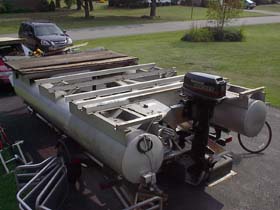
 Photo 1: 7/30/2005 Photo 1: 7/30/2005
After the completion of the bicycle power prototype testing, the entire semi-rotten deck of the old pontoon boat was removed entirely. This made room to install a sound platform on which to build a structure that would house a bicycle propulsion system as well as an accommodations space for a crew of 2-3 people.
|
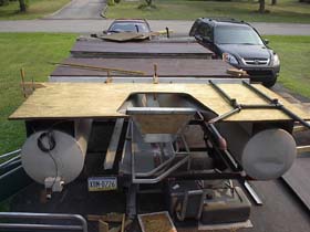 Photo2: 8/03/2005 Photo2: 8/03/2005
With the old deck removed, new plywood was placed onto the aluminum support structure. The original deck was 5/8" thick CCX treated plywood. The plywood used for the new deck was a 3/4" ACQ treated plywood, which is a newer type of preservative that contains less arsenic than the older CCX variety. The best plywood for this application would have been 3/4" marine grade CCX plywood, which is still available from certain dealers for marine related applications, but is also quite expensive. Marine plywoods have no voids between the plys of the wood and are therefore much stronger and less prone to rotting than normal exterior grade plywoods found in your local lumber yard. However, in this case, the cost would have been nearly three times as much to use the best materials, so I deferred to using lower quality materials that will most likely begin to rot in 10-15 years. Marine Plywood with CCX pressure treatment would most likely last at least 40 years from what I have read. The bottom side of the plywood will be in constant contact with the splashing water of the river, so an extra sealant (brown in color) was painted to the underside of the wood before it was screwed in place on the aluminum frames. Also in this photo is the beginning of the frame made of 1" pipe that will support the bicycle propulsion system.
|
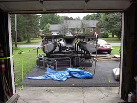 Photo3: 8/04/2005 Photo3: 8/04/2005
Before the entire new plywood deck could be laid down, a support structure needed to be added to the bow to give the vessel a slightly larger deck area. In order to accomplish this, the boat had to be moved back about a foot on its trailer. Moving a boat of this size while out of the water with only one person provides an interesting challenge. To accomplish this, two nylon ratchet straps were tied around the walls of the garage door structure. A rope was passed around the transom of the boat and tension was applied to the rope using the ratcheting straps. Using nylon ratcheting straps in this manner could cause them to fail, or also possibly pull down the walls of the garage door support. Luckily, neither of these happened this time around! With the ratcheting straps providing a steady tension on the stern of the vessel pulling aft, a gentle upward push on the bow would cause the boat to slide about one inch backwards on the trailer. This process was repeated several times to move the boat back the required foot in order to install the bow support structure.
|
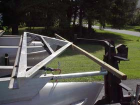 Photo 4: 8/04/2005 Photo 4: 8/04/2005
Here's a photo of the bow support structure which consists of some 1" galvanized pipe bolted on to the aluminum frame of the vessel with a treated 2x2 spanning the width. The galvanized pipe was first wrapped in a piece of old bicycle inner tube before bolting it to the aluminum to minimize galvanic action between the dissimilar metals. This structure did not actually lengthen the deck of the boat, but instead added space in the shape of a triangle in both corners of the bow. These additional triangles provided a total of about 8 square feet of extra deck space, which is significant considering the total area of the accommodations space is only about 90 square feet. An extra 10 percent of usable deck space can go a long way!
|
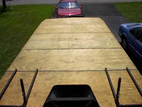 Photo 5: 8/04/2005 Photo 5: 8/04/2005
This is a photo of the completed new deck. All seams and edges were sealed with roofing tar to deter moisture from seeping into the end grain and beginning the process of rotting. The support structure for the bicycle propulsion system, mad of 1" threaded pipe and fittings, is shown bolted to the aft part of the deck. This structure is bolted through the plywood and aluminum support beams that run athartwships in six different places, making it very securely attached to the vessel
|
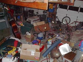 Photo 6: 8/04/2005 Photo 6: 8/04/2005
As the vessel is being constructed, the garage of the driveway in which it sits becomes a staging area for future elements of vessel construction as well as a collection point for supplies and resources for the upcoming voyage. A string bass, pieces of bicycles, a drill press, a cooler donated by the next door neighbor all are a part of the chaotic mess that goes along with the building of a bicycle powered river vessel!
|
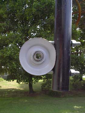 Photo 7: 08/04/2005 Photo 7: 08/04/2005
In considering what kind of bearing to use for a paddlewheel system, the first inclination was to go with this idler pulley held in place be a U-bolt. This relatively simple construction used parts that seemed sturdy and could be easily replaced should the need arise.
|
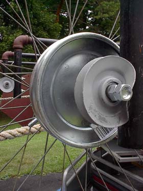 Photo 8: 08/04/2005 Photo 8: 08/04/2005
Installation of the idler pulley bearing revealed that the sidewalls of the pulley were not constructed of thick enough steel to retain its shaped when clamped down on with the U-bolt. A good idea in theory, but as often is the case, doesn't pan out into an effective implementation.
|
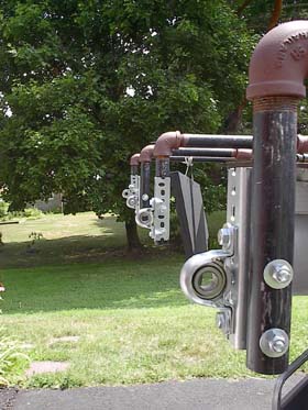 Photo 9: 08/05/2005 Photo 9: 08/05/2005
The solution to this bearing problem was solved with a setup that was better, and believe it or not less expensive than the first! A cheap pillow block housing clamps down on a standard, inexpensive bearing that bolts onto a pre-drilled piece of angle stock. This setup uses commonly available parts from a tractor supply store, and has the added benefit of vertical adjustment of the paddlewheel at a later date if necessary. It is also quite strong and rugged, which is important for a paddlewheel hanging off the stern of a vessel.
|
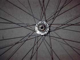 Photo 10: 08/09/2005 Photo 10: 08/09/2005
The paddlewheels themselves are constructed of old bicycle wheels connected together around the rim with six pieces of treated 2x2 lumber. All of the wheels used in the paddlewheel construction are rear wheels, which have a shaft diameter of 7/16". Front wheels on a bicycle have a slightly smaller shaft diameter, about 3/8", so using all rear wheels in the paddlewheel design allows for a larger, stronger axle. Pictured here is a nut that was welded onto the rear wheel hub through which the axles, simply a piece of 7/16" threaded rod, will pass.
|
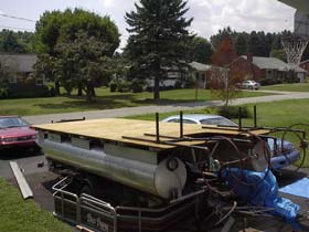 Photo 11: 08/09/2005 Photo 11: 08/09/2005
Here's a photo of the early paddlewheels threaded onto their axles and attached in place on the support frame on the stern of the vessel. On the outboard side of each wheel there is v-belt pulley that will be used to connect the paddlewheel to the bicycle. The drive system is hybrid in nature in that there is a v-belt going from the paddlewheel to an intermediate shaft which also has on it a chain to connect to the drive train of the bicycle.
|
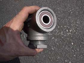 Photo 12: 08/10/2005 Photo 12: 08/10/2005
In considering how to make an intermediate shaft, it just so happened that some bearings that had been picked up for no particular reason one day at the auto parts store fit perfectly inside a 1-1/4" pipe T-fitting with only a small amount of reaming! This "shaft housing" fitting attaches easily to the bicycle support structure with a 1-1/4" to 1" reducing bushing.
|
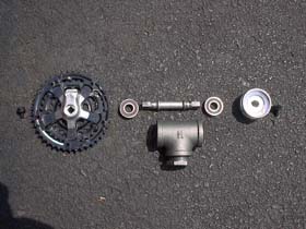 Photo 13: 08/10/2005 Photo 13: 08/10/2005
Here's an exploded view of the intermediate shaft assembly, which uses an old style bottom-bracket shaft from a bicycle. It is also quite coincidental that the bearings that had been picked up for no particular reason at the auto parts store also happened to have an inside diameter that fit perfectly over bottom bracket shaft, and also was the proper length to fit inside the 1-1/4" T-fitting pictured above. It is interesting how sometime random pieces from different walks of life can join together in harmonious union. A 5/8" inner diameter v-belt pulley fits over one end of the protruding bottom-bracket shaft, and a standard 3-geared bicycle chain-ring set with the crank arm sawed off gets pressed onto the other side.
|
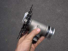 Photo 14: 08/10/2005 Photo 14: 08/10/2005
Here's the intermediate shaft unit completely assembled. Having three different sized chain rings will be helpful to fine tune the gearing of the system and also provides an easy ways to attach accessories to the system, such as a bicycle powered battery charger.
|
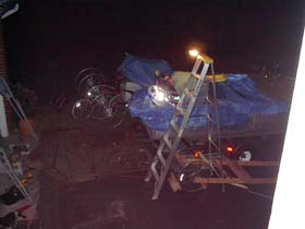 Photo 15: 08/10/2005 Photo 15: 08/10/2005
After all of the parts and pieces are threaded together in the proper position, my friend Jaret Lynch brings his welder over and helps to permanently attach many of the pipes and fittings to each other. Some of the threaded pipe fittings do not need to be welded because they are held in place by the design of the frame. Other fittings on the frame will be subject to torque that will cause the threaded fittings to twist and lose their precise position, so it is these joints that are being welded.
|
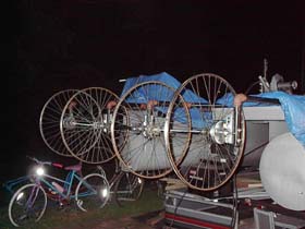 Photo 16: 08/10/2005 Photo 16: 08/10/2005
Here's what everything looks like once the welding is complete; this is a solid, rigid frame with sound bearings ready to accept a bicycle drive input and some paddlewheel blades that will move the boat through the water.
|
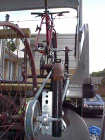 Photo 17: 08/15/2005 Photo 17: 08/15/2005
Here's a closeup of the drivetrain with the bicycle mounted showing the belt connecting the paddlewheel to the intermediate shaft.
|
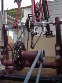 Photo 18: 08/15/2005 Photo 18: 08/15/2005
This is a photo showing how the intermediate shaft connects to the bicycle. It is interesting to note that no modifications have been made to the bicycle itself. The bicycle can actually be removed from the system and ridden about on land when proper wheels are attached, and indeed a spare set of wheels are stored on the boat for use while in port. Furthermore, any bicycle could be mounted in the support structure and be used to power the paddlewheels. The bicycle is held in place with a simple clamping device made from 3/4" threaded rod, coupling nuts, and a wing nut for quick release. The intermediate shaft is mounted to the support structure via four bolts that pass through slotted holes, thus serving as a chain tensioner between the intermediate shaft and the rear bicycle hub. The rear bicycle hub is a custom configuration made of a standard 7-speed Shimano Hyperglide cassette. A small cog is placed all the way on the inside of the cassette which serves to connect the cassette directly to chainrings on the intermediate shaft and hence the paddlewheels. Normal sized cogs are placed next to the small cog on the inside, which allows for relatively normal shifting of the bicycle's gears, resulting in different paddlewheel speeds given the same pedal cadence input. Since all cogs are on the same cassette, there is no "free-wheeling" effect that is normally found on most geared bicycles. As the paddlewheel turns, so do the pedals of the bicycle, and vice versa. If desired, the chain can be broken and threaded onto a fixed gear so that it does not pass through the derailleur of the bicycle. This in effect adds a "reverse gear" to the paddlewheel and allows the bicyclist to pedal forwards or backwards to move the paddlewheel in a likewise fashion.
|
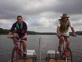 Photo 19: 08/18/2005 Photo 19: 08/18/2005
Here is a record of the first sea trial of the second generation bicycle powered propulsion system on Lake Somerset in Somerset, PA. Pictured are me and my brother, Jeff (on the left) testing out the new system. We find that it works pretty well. The spinning paddles move the boat easily through the water. With two people riding, steering can be accomplished by pedaling faster on one side than the other when the paddlewheels are set up independently of each other. Or, if the bicycle chain is set up to bypass the bicycle's derailleur, one person can pedal forwards and the other can pedal backwards for an even tighter turning radius. (Note: in this photo the paddlewheels are not operating independently of each other, but rather they are connected by the "Dogbone" which is described in the next logbook entry. The Dogbone would not be attached to achieve the operation as described in this entry).
|
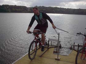 Photo 20: 08/18/2005 Photo 20: 08/18/2005
Here, Jeff demonstrates that one person can power the vessel as well. In this scenario, the two wheels are linked together with a part that has been coined "The Dogbone" for its similarity to the favorite toy of man's best friend. The Dogbone connects the wheels together so that one bicycle turns both wheels simultaneously. In this scenario, steering is accomplished by a rudder and tiller assembly that was added to the underside of the transom of the vessel. Two people can still pedal simultaneously with the Dogbone connected if so desired, however steering capabilities in this scenario must remain with the rudder.
|
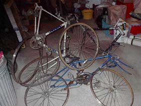 Photo 21: 08/20/2005 Photo 21: 08/20/2005
These bicycles were harmed during the making of this vessel.
|
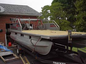 Photo 22: 08/25/05 Photo 22: 08/25/05
With the sea trials of the second generation bicycle prototype complete, work began to complete the accommodations space of the vessel. Some of the original pieces were used in this process. For example, the two pieces of aluminum on the stern of the vessel were remounted, but the original port piece was mounted on the starboard side, and the original starboard side was mounted on the port. This proves the notion that sometimes things work better backwards the second time around. In this photo, we've also re-attached the bimini top which should provide a great shade on sunny days. Also, the original aluminum edging was placed around the perimeter of the deck to strengthen the structure and also give it a more finished look.
|
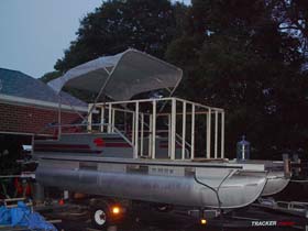 Photo 23: 08/26/05 Photo 23: 08/26/05
As night begins to fall, the frame of the accommodations space begins to take shape. The primary building material for the structure was a pine 2x2, which weighs have the amount of a 2x4. Weight on the vessel is a very important consideration. If there is too much weight, it is a fact of nature that the vessel will sink. Keeping track of the weight added to the vessel is an important part of the vessel design.
|
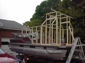 Photo 24: 08/28/05 Photo 24: 08/28/05
Here, the frame goes up for the galley and head (bathroom) areas in the forward part of the vessel. Keep in mind, this is quite a small boat! It's only about 18 feet long on deck and 8 feet wide overall. The accommodations space is just over 6 feet long, the galley area is about 2.5 feet long, and the front porch is about the same. The remainder of the boat's length is taken up by the bicycles on the stern. The paddlewheels hang off the back of the vessel, making the boat's overall length about 21 feet. The height of the accommodations space is about 3 feet 9 inches and the height of the galley area is just an inch taller than myself, about 6 feet 3 inches off of the deck.
|
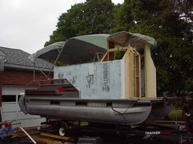 Photo 25: 08/30/05 Photo 25: 08/30/05
The vessel is sheathed with blue Styrofoam on the sides, which serves as an underlayment for vinyl siding. The vinyl siding that will go on the sides is lighter than the alternative 1/4" plywood sheathing that might be applied in its wake. The siding also has the benefit of keeping us warmer, dryer, and does not need to be painted, and will not rot. I am not normally a big fan of vinyl siding, but it works great in this application at only a slightly more cost than the 1/4" plywood alternative. This photo also shows the semi-circle roof that has been mounted on the top of the galley. The sides of the galley structure have been cut away to ensure good visibility from a seat atop a bicycle. To this end, a large picture window was added in the center of the galley structure so that forward vision from the aft deck would not be impaired.
|
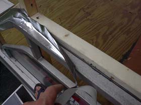 Photo 26: 08/31/05 Photo 26: 08/31/05
To prevent leakage at the interface of the metal and the wood, this rubber flashing tape that is often used for sealing around windows and doors was used to make a water-tight seam. When trying to make things waterproof, you always have to think like a drop of water thinks and try to layer pieces of a structure accordingly
|
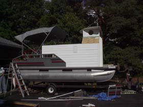 Photo 27: 09/03/05 Photo 27: 09/03/05
Here the vinyl siding is nearly completed. 1/4" luan plywood was used on the structure where it was not practical or aesthetically pleasing to use the siding. You may also notice that the original "Suntracker Bass Buggy" vinyl decal has been peeled off of the sides to make way for new custom vinyl stickers that reflect the name and purpose of the vessel. A paint scheme of white, black and gray to match the original color scheme of the vessel was decided upon.
|
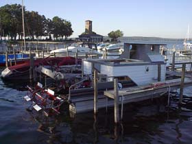 Photo 28: 09/07/05 Photo 28: 09/07/05
Here's a photo of what the vessel looked like a couple of days after it was officially launched onto Chautauqua Lake over Labor Day weekend 2005. It is beginning to look like a boat of some sort. Notice the vinyl decal of the dragonfly and the organization's logo on the side of the vessel. The name of the vessel is Libelula , which is a Spanish word for and a latin genus of the illustrious odontan.
|
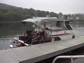 Photo 29: 09/19/05 Photo 29: 09/19/05
Here's a photo of the vessel alongside a dock in East Brady, PA. The boat is coming together, nearing completing. A tarp can be placed of the accommodations space as a roof to keep the area dry during foul weather. During times of fair weather, the accommodations space can be and open cockpit.
|
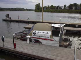 Photo 30: 10/06/05 Photo 30: 10/06/05
The vessel in Marietta, OH shows a tent that has been modified to fit over the opening in the top of the accommodations space. This tent-top and its accompanying rainfly provide enough height in the accommodations space to walk around comfortably. In times of extreme wind and rain, the tent can be taken down and replaced with a tarp to offer less resistance to the wind while still maintaining waterproof integrity.
|
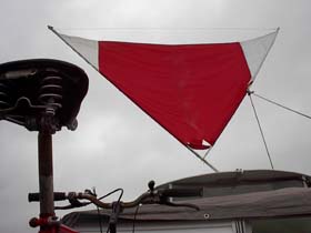 Photo 31: 10/09/05 Photo 31: 10/09/05
Here's a shot of the vessel's sail in action! The sail is stepped into the roof of the galley structure, and supported by a hole drilled through two 2x4 pine pieces sandwiched together. Sailing on the river is difficult because rarely is the wind steady or the river straight. Furthermore, the vessel is really only designed to sail with a downwind breeze, which greatly limits the occasions for which the sail can be used. However when the conditions are right, it never hurts to have an extra little push from the wind!
|